

代码拉取完成,页面将自动刷新
Author: Filip Geib, Maintainer: septentrio-gnss Website: https://github.com/septentrio-gnss/mowi License: CC BY-SA 4.0 & OSHW Definition 1.0
Mowi is an Open Source hardware project that combines a compact Septentrio's GNSS receiver mosaic with a wireless ESP32 Wrover module. This extension enables mosaic to access wireless internet, receive remote commands, or use real-time corrections. The communication between the mosaic and the ESP is provided throughout a standard 802.3 Ethernet link. In-build USB HUB allows a user to connect to mowi with a single USB cable while accessing both the mosaic's and ESP's communication interface.

To support an easy-to-use evaluation and offer a high connectivity, the mowi exposes various interfaces. This includes four JST lock connectors compatible with Pixhawk, external GNSS, or other Septentrio's modules. Shared USB micro B port with an ESP dedicated autoflash circuitry for convenient programming. Support of single or dual antenna setup in MMCX or U.FL connectors. In-build eMMC device for easy data logging. And a separate SMA connector for an external WiFi/Bluetooth antenna. On top of that, the mowi comes with various perks, such as indication LEDs, selectable TTL voltages, or support for external sensors and other advanced circuitry.

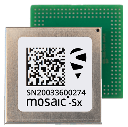
Mosaic modules are Septentrio's small-size and low-power GNSS receiver modules ideal for providing highly accurate positions. Mosaic modules integrate the latest generation of GNSS technology, delivering highly accurate positions with minimal power consumption. While compact in size they fully retain the high-reliability and exceptional accuracy performance that Septentrio receivers are known for. True multi-frequency multi-constellation technology gives our module receivers access to every possible signal from all available GNSS satellite constellations including the U.S. GPS, European Galileo, Russian GLONASS, as well BeiDou, QZSS and NavIC. Septentrio’s advanced field-proven algorithms exploit this signal diversity to deliver maximum positioning availability and reference network compatibility. The mosaic's product range comes with three different versions. Their key features and differences are listed in the following table:
| GNSS modules | mosaic-X5 | mosaic-H | mosaic-T |
|---|---|---|---|
| Use case | base/rover | heading | timing |
| Dual antenna | |||
| Heading | |||
| L-band | |||
| RTK | |||
| Timing receiver |
Few external attachments have to be provided to enable mowi's full functionality. The following list sums them up. Note that it is not necessary to follow the order.
E.ANT designator.E.ANT. This antenna should be explicitly designed for the 2.4 GHz band and facilitate a male SMA connector.MAIN. An ordinary talisman antenna was used through the following examples.AUX.

![]() Steps 1. and 2. can be skipped when mowi with the ESP32-WROVER-E module is used. As this module facilitates an inbuild WiFi antenna, there is no need for an external one.
Steps 1. and 2. can be skipped when mowi with the ESP32-WROVER-E module is used. As this module facilitates an inbuild WiFi antenna, there is no need for an external one.
The easiest way of communicating with mowi is through its USB interface. This example shows how to do so step by step while illustrating and explaining some basic functionality of the mosaic and ESP modules.
Connect mowi to your PC using a USB micro-B cable. Once attached, you should be able to see three new USB devices in your system. If you are using Linux, their drivers are installed automatically. On a Windows machine, you have to install one of the drivers manually. Download and install CP210x Universal Windows Driver from the ESP's UART bridge manufacturer website. After doing so, you can check these new USB devices in Windows Device Manager. On Linux, open a terminal and run lsusb command. You should see something similar to the following image, where the unblurred devices correspond respectively to i) ESP's UART bridge, ii) mosaic module, and iii) mowi's USB HUB:

By default, the mosaic module supports Ethernet-over-USB. Therefore the easiest way how to access its information and configuration is through your internet browser. To do so, simply open the 192.168.3.1. IP address in your favorite browser and automatically enter the mosaic's web interface. In a case of a happily running mowi, you should see something similar:

Another simple option of communication with the mosaic module is through its COM ports. These ports should be visible in your system as ACM0 and ACM1. Use your favorite serial terminal (such as Putty or Moserial) and the following settings to establish a connection:
| port | baud rate | data bits | stop bits | parity | flow control |
|---|---|---|---|---|---|
| ACM0 / ACM1 | 115200 | 8 | 1 | no | none |
Now you can command mosaic with a command line interface outline. For more information about syntax, replies, and commands tables, check section 3.1 in mosaic-X5 Reference Guide. To quickly test this interface, you can command mosaic to turn the GP1 LED on and off. To do so, send the following two commands throughout the serial terminal:
$ sgpf, GP1, Output, none, LevelHigh
$ sgpf, GP1, Output, none, LevelLow
Not only the green GP1 LED goes on and off again, but you should also see the following mosaic's response in your serial terminal:

After successfully establishing communication with mosaic, the ESP module is the last remaining challenge. Thanks to the mowi's inbuild UART bridge, the communication can be established through a USB0 COM port. Use again your favorite serial terminal with the following parameters:
| port | baud rate | data bits | stop bits | parity | flow control |
|---|---|---|---|---|---|
| USB0 | 115200 | 8 | 1 | no | none |
After establishing this connection, you should be able to receive debug data from the ESP module. By default (from factory), the ESP32-WROVER is flashed with Espressive's ESP-AT command firmware. To quickly test this interface, you can press the ESP's reset button designated by E.RST. After doing so, you should see a reboot log similar to this one:

![]() On Windows systems, mosaic's and ESP's ports are usually named
On Windows systems, mosaic's and ESP's ports are usually named COMx, where x stands for a randomly assigned number. Use Control Panel >> Device Manager >> Ports to determine which USB device is linked o which port (or brute-force it).
![]() The Espressive's ESP-AT firmware does not support the ESP's UART0 by default. Therefore, sending AT commands through the USB interface with the ESP's default factory firmware is impossible.
The Espressive's ESP-AT firmware does not support the ESP's UART0 by default. Therefore, sending AT commands through the USB interface with the ESP's default factory firmware is impossible.
The true potential of mowi lies in running custom firmware on the ESP module. The most convenient way is to flash ESP with an already compiled binary image using Espressive's official esptool.py utility. If you are interested in building your own firmware, please skip to the following example (Developing ESP firmware) as it handles the flashing process for you.
To start flashing, you have to install the esptool utility. You can do so from pypi repository by using the pip packet management system. Mind that you need Python 2.7 or Python 3.4 or newer installed on your computer. For more details or to troubleshoot problems, visit the esptool's GitHub repository. To install the esptool run the following command in your terminal:
$ pip install esptool
During experimenting with ESP, it might be useful to re-flash it with the default (factory) firmware known as ESP-AT. To download this firmware go to its official GitHub repository and download the .zip folder dedicated to ESP32-WROVER module. After unzipping it, enter the .\factory subfolder and search for factory_WROVER-32.bin. This is the binary image you are about to flash to your ESP. To do so, connect your mowi to your computer via the USB cable and execute the following command in your terminal:
$ esptool.py --chip auto --port /dev/ttyUSB0 --baud 115200 write_flash -z 0x0 factory_WROVER-32.bin
Where --port specifies a serial port to which ESP is connected, --baud is the default baud-rate, 0x0 is a targeted memory address, and factory_WROVER-32.bin is the binary image you are flashing to ESP. After successful flashing, you should see a similar log in your terminal. The Hash of data verified. message means that the flashed image was successfully verified.

![]() Mowi's built-in auto-download circuitry will set the appropriate boot mode and reset the ESP module for you. If you wish to control these processes manually, use two tactile switches designated as
Mowi's built-in auto-download circuitry will set the appropriate boot mode and reset the ESP module for you. If you wish to control these processes manually, use two tactile switches designated as E.RST and E.BOOT. Holding down E.BOOT and then pressing E.RST initiates firmware download. Standalone press of E.RST resets the ESP module.
![]() The previous flash command is a minimal working example. For advanced flashing, please refer to flash modes in the esptool's manual. A more robust flashing can be executed with this command:
The previous flash command is a minimal working example. For advanced flashing, please refer to flash modes in the esptool's manual. A more robust flashing can be executed with this command:
$ esptool.py --chip auto --port /dev/ttyUSB0 --baud 115200 --before default_reset --after hard_reset write_flash -z --flash_mode dio --flash_freq 40m --flash_size 4MB 0x0 factory_WROVER-32.bin
In this project, we provide not only the hardware design but also an example firmware. These examples are intended to demonstrate key features of mowi and deliver code that can be further used and modified. Espressifs ESP-IDF is used as a development framework. The following examples are currently available:
examples/mowi_wifi_basic WiFi to Ethernet packet forwardingexamples/mowi_wifi_client WiFi to Ethernet packet forwarding with BLE based ProvisioningAn example named mowi_wifi_basic extends mosaic with full access to wireless internet by transparently forwarding internet packets.

The objective is to demonstrate how to set up an internet packet forwarding between mosaic's Ethernet and ESP's WiFi with respect to mosaic's MAC address. The ESP module is configured as a WiFi station connecting to a WiFi access point and forwarding all traffic to and from mosaic's Ethernet port. No actions are performed by ESP on layer 3 and higher layers. It is therefore expected that the targeted WiFi access point runs a DHCP server.
The step-by-step functionality of this example can be described as follows:
To run this example, you need to flash mowi with provided firmware. Credentials of the targeted WiFi access point are hardcoded in this case to mowi_wifi_accpoint as an SSID and mowi_rocks as a password. If you are okay with it, you can directly flash provided binaries. If not, you can easily modify the menuconfig file and recompile the code. Please refer to steps 7 to 9 of ESP-IDF Get Started for more information.
After a successful connection to WiFi (indicated by the blueWIFI LED), you can reach the mosaic's WEB interface through an IP address assigned by the DHCP server. To figure it out, you can:
Communication >> Ethernet section of the mosaic's WEB interface through the USB connection.$ getIPSettings command to mosaic through one of the provided COM ports.mowi_wifi_basic: WiFi connected with IP Address:192.168.43.189
To flash the provided binaries, connect mowi to your computer, navigate to examples/mowi_wifi_basic/build, and execute the following command (replace PORT accordingly to your system):
esptool.py -p PORT -b 460800 --before default_reset --after hard_reset --chip esp32 write_flash --flash_mode dio --flash_freq 40m --flash_size detect 0x10000 mowi_wifi_basic.bin 0x1000 bootloader/bootloader.bin 0x8000 partition_table/partition-table.bin
An example named mowi_wifi_client adds a Bluetooth based WiFi provisioning to the previously mowi_wifi_basic example.
A drawback of the previous example is its hardcoded WiFi access point SSID and password. In some applications, it might be beneficial to change WiFi credentials to-go instead of recompiling and reflashing the firmware. In this example, we illustrate how to use Espressives Unified Provisioning API to set up ESP's targeted access point through Bluetooth with a smartphone. This is done via the Espressives BLE app available at:
To start with this example, open the BLE Provisioning app and click on Provision New Device. There are two different ways how to proceed. The first one is thoughts scanning QR codes generated by ESP. This code is displayed in its firmware log. Connect mowi to your computer through the USB and open the ESP's COM port in your favorite serial terminal. Press the E.RST button to reboot the ESP module. After a while, your log stream should stop and display a similar QR code:

The second option is through searching for available Bluetooth devices. Press I don't have a QR code and wait for the search to complete. You should see your mowi listed as PROV_MOWI_MAC where MAC is your mowi's actual MAC address. Click on it and just confirm the default proof of possession PIN (abcd1234) by pressing Next.
After this successful connection, the ESP module will automatically search for available WiFi networks and report findings to your BLE app. Now you just have to select your desired WiFi network and enter its password. The ESP module will then automatically connect to it and forwards all internet packets to and from the mosaic. An example of both Bluetooth and WiFi network searches could be:


It is recommended to erase flash specially if mowi had been already flashed before. You can do this by using the following command: esptool.py -p PORT erase_flash
To flash the provided binaries, connect mowi to your computer, navigate to examples/mowi_wifi_client/build, and execute the following command (replace PORT accordingly to your system):
esptool.py -p PORT -b 460800 --before default_reset --after hard_reset --chip esp32 write_flash --flash_mode dio --flash_freq 40m --flash_size detect 0x10000 mowi_wifi_client.bin 0x1000 bootloader/bootloader.bin 0x8000 partition_table/partition-table.bin
At this moment, no third party is known, to the author or Septentrio, to be selling manufactured versions of the mowi board. However, anyone can use the reference design in the form of the KiCad project and contact his preferred manufacturer for production. The mosaic GNSS modules can be obtained directly from Septentrio or Digi-Key. The mosaic's Digi-Key part numbers are 2771-410322-ND for mosaic-X5 and 2771-410352-ND for mosaic-H.
![]() In order to maintain the PCB's designed impedance matching, all of it's six layers should be manufactured in 35µm copper thickness.
In order to maintain the PCB's designed impedance matching, all of it's six layers should be manufactured in 35µm copper thickness.
Within this project, we have used the manufacturing and assembly services of Eurocircuits. In case of interest in using their services to produce the mowi, please find already processed production data in .\fabrication\eurocircuits. These files can be uploaded directly to Eurocircuits and boost the process of PCB validation and assembly analysis.
![]() Disclaimer: This project is PROVIDED AS IS and has not been fully validated nor by the author nor by Septentrio. It remains your responsibility when producing or using this design for your own purposes.
Disclaimer: This project is PROVIDED AS IS and has not been fully validated nor by the author nor by Septentrio. It remains your responsibility when producing or using this design for your own purposes.
A 3D model of mowi's housing designed to be printed by a 3D printer is available in mowi/designFiles/housing. Two STL files: mowi_topprint_housing.stl and mowi_lowerprint_housing.stl can be loaded directly into a slicer software. The model can be used with for M3x8 screws that would self-thread into the plastic. If needed, brass threaded inserts can be added with a simple modification of the holes in the top mowi_topprint_housing.stl. Holes for LED's are not included in the model as many 3D printers are not very good at these small details. If needed, the hole can be drilled after printing or added to the STL model. Overall, this should be quite a simple print.

This housing was designed and evaluated by Silviu Taujan as a contribution to the mowi project.
This project makes the following deliverables for both integrators and designers of systems around Septentrio's mosaic modules.
| Path | Description |
|---|---|
mowi/3Doutput/ |
Rendered RWL and STP 3D models of the mowi. Basic .png exports included. |
mowi/designFiles/ |
Efuse calculator .xlsm scheet, mowi's formfactor .svg templates and STP 3D models of housing ready to be printed. |
mowi/fabrication/boms/ |
Vanilla KiCad and slightly modified .csv bills of material togehter with InteractiveHtmlBom .html bom. |
mowi/fabrication/eurocircuits/ |
Should include ready-to-order EuroCircuits files in the recent feature. |
mowi/fabrication/gerbers/ |
Exported gerber files of the mowi board. |
mowi/library/Septentrio_<xxx>.pretty/ |
Septentrio's KiCad footprints libraries divided into groups denoted by <xxx>. |
mowi/library/Septentrio_packages3D/ |
STP 3D models linked to Septentrio's KiCad footprints libraries. |
mowi/library/Septentrio_symbols/ |
Septentrio's KiCad symbols library. |
mowi/readmeSource/ |
Source files for this readme file. |
mowi/schematic/ |
Electrical schematics .pdf export. Separate sheets and merged version present. |
The following section lists the most important design specifications of the mowi board. For a detailed understanding, please refer to the schematic files in .\schematic.
To support an easy-to-use evaluation and offer a high connectivity, the mowi exposes various interfaces.
UART0. Additional auto-download circuitry is controlled by the FTDI chip enabling easy and convenient flashing. However, two reset and boot buttons, typical for the ESP applications, are available if a flash through UART is preferred or a manual reboot is needed.COM1 port with HW flow control, and ii) universal mosaic connector offering additional functionality of external trigger EventA, precise timekeeping with PPS output PPSO and communication via COM3 port. The last JST connector is dedicated to ESP and exposes its UART1 with HW flow control. One of the possible use cases for this connector is a link to an external GSM module.The images below show the pinout of the mowi’s connectors (and LEDs). Even though most of the labels follow the mosaic’s and ESP’s datasheets, the following remarks are required: LED PWRLED become active when the main 3.3V power line is active, LED WIFILED is driven by ESP's pin IO12, and LED BTLED is driven by ESP's pin IO13.

Expect the main connectors, two auxiliary 2.54mm headers are present. The ADV stands for 'advanced' and belongs to the mosaic, while SENS means 'sensors' and connects to the ESP. Remarks: ESP SEN. VP and ESP SEN. VN connect to the ESP’s SENSOR_VP and SENSOR_VN pins respectively, and are input only. Pins ESP SCL and ESP SDA are connected to ESP’s IO14 and IO15 respectively. They are labeled as an I2C data bus, however, they might be used as GPIOs. Mind the integrated 4.7k pullups on these I2C pins.

These images serve mostly as a fast lookup reference. For a proper understanding of internal wiring and connections, we recommend referring to schematic files in .\schematic.
The mowi board can be powered with a 3.3V or 5V power supply connected to any of the JST connectors or the USB port. The recommended minimum power supply output current is 1.2A. The maximal input current should not exceed 2.1A under any circumstances. The individual power input pins are connected to a single input power bus throughout series of diodes. An electronic fuse device continuously monitors this input bus for events of over voltage, over current, and a short circuit.
It is possible to change TTL voltages of signals break out to the JST MSCand ESP connectors, and the ADV header. This can be done using a TTL selector switch separately for pins assigned to the mosaic, and the ESP. The available voltage levels are 3.3V and 5V. Please mind, that the JST PXH connector and the SENS header are 3.3V TTL only. The image below illustrates the TTL switch positions, while the table sums TTL voltage options:

| Connector | TTL option | TTL switch marking |
|---|---|---|
JST PXH
|
3.3V | na |
JST MSC
|
3.3V or 5V | M |
JST ESP
|
3.3V or 5V | E |
ADV header |
3.3V or 5V | M |
SENS header |
3.3V | na |
All of the previously mentioned connectors together with the GNSS antenna connectors, and the USB port are protected against ESD events. The clamping voltage of protection devices is always set to the protected bus's maximal operational voltage. That means 3.3V for the PXH connector and the SENS header, and 5V in all other cases.
The mowi's shape, size, and mounting are based on the AsteRx-m3 standard developed by Septentrio N.V. This formfactor compatibility enable mowi to be used with another Septentrio products, such as AsteRx-i D UAS or evaluation kit. The drawing below defines the AsteRx-m3 formfactor overall size and mounting:

The following two drawings define mowi's shape and positions of individual connectors / LEDs:


All dimensions marked in the previous drawings are in millimeters. For the exact shape please refer to .\designFiles\formfactor_top.svg and .\...\formfactor_bottom.svg, or check directly the KiCad Pcbnew file .\mowi\mowi.kicad_pcb.
Because of the formfactor size restrictions and a user-friendly layout, all of the supporting circuitry was placed from the bottom side of the mowi board. The only exception to this statement is the GNSS signal circuitry, populated and routed on the board's top side. This approach was determined by the controlled impedance requirements of this critical signal. The image below roughly illustrates the layout of separate subsystems:

Legend: 1A and 1B - Ethernet PHYs of mosaic and ESP, 2 - USB HUB, 3 - FTDI bridge of ESP, 4 - eMMC device of mosaic, 5A and 5B - 3.3V buck/boost converter with eFuse and 5V boost converter, 6 - signal logic gates, TTL voltage translators and ESD protection devices, 7 - LED drivers.
此处可能存在不合适展示的内容,页面不予展示。您可通过相关编辑功能自查并修改。
如您确认内容无涉及 不当用语 / 纯广告导流 / 暴力 / 低俗色情 / 侵权 / 盗版 / 虚假 / 无价值内容或违法国家有关法律法规的内容,可点击提交进行申诉,我们将尽快为您处理。
1. 开源生态
2. 协作、人、软件
3. 评估模型


